
Modelling wind turbine acoustics to design quieter wind farms
Noise is one of the main reasons wind farm projects face resistance from nearby communities. For developers and OEMs, it is not enough to rely on rule of thumb calculations. You need acoustic models that can explain, predict and help reduce tonal and broadband noise from modern, large scale turbines.
At Xi Engineering Consultants, we use advanced simulation tools to model how turbines vibrate and radiate sound, then translate those results into clear guidance for design, planning and operation.
Why wind turbine noise matters for projects
Broadband and tonal noise from wind turbines does not just affect acoustic comfort. It can:
- Increase annoyance for people living near wind farms and impact perceived quality of life
- Trigger planning constraints, curtailment or penalties if noise limits are breached
- Delay projects where the acoustic case is not clearly evidenced
Tonal components are often the main source of complaints, because the ear is very sensitive to narrow band tones compared with broadband background noise.
Good acoustic modelling helps you:
- Understand where those tones come from
- Test mitigation options before you build
- Demonstrate compliance with standards and planning conditions
Where tonal noise from wind turbines comes from
Wind turbines generate several types of sound:
- Aerodynamic noise from the blades moving through turbulent air
- Mechanical noise from the drivetrain and generator
- Structural radiation from large steel components such as the tower
Tonal noise is most often linked to periodic vibration in the drivetrain. A key source is the meshing of gear teeth in multi stage gearboxes. Typical gear mesh frequencies include:
- Low speed stage – around 10 to 30 Hz
- Intermediate stage – around 50 to 150 Hz
- High speed stage – around 300 to 700 Hz
If those excitation frequencies line up with structural resonances in the tower or blades, even relatively modest internal forces can produce clearly audible tones at receptors hundreds of metres away. Tall, lightly damped steel towers are particularly effective radiators because of their large surface area.
When you put that together with sensitive receivers and low background noise in rural locations, you have a strong case for detailed, physics based modelling.
Why modelling acoustics from large turbines is so challenging
From a simulation perspective, wind turbines are an awkward combination:
- Very large, slender structures
- Large regions of air and void space around blades and tower that must be included in the acoustic domain
- Tonal noise at frequencies where wavelengths are no longer large compared with the structure
In a conventional finite element analysis (FEA) approach:
- You create a model of the structure and a surrounding volume of air
- That volume is divided into many small elements
- To represent sound accurately, each wavelength needs several elements across it (a common rule of thumb is around one sixth of a wavelength per element)
The problem is that as frequency increases, wavelength decreases:
- At 100 Hz, sound in air has a wavelength of about 3.4 m, so element sizes of roughly 0.5 to 0.6 m are needed
- At 1000 Hz, the wavelength is around 0.34 m, so element sizes closer to a few centimetres are required
For a turbine with a rotor diameter over 150 m and a tip height exceeding 200 m, that can lead to millions of elements in the acoustic mesh. Memory demand and solve time grow rapidly, to the point where full 3D FEA at higher frequencies becomes impractical.
That is why the choice of modelling approach matters just as much as the model geometry.
Two main approaches: FEA and BEM
Two of the most useful methods for simulating wind turbine acoustics are finite element analysis (FEA) and the boundary element method (BEM). Each has strengths and limitations.
FEA: powerful but mesh hungry
FEA is well suited when you need to model:
- Structural dynamics and acoustics in a coupled way
- Low to mid frequencies where mesh sizes are still manageable
- Near field phenomena close to the turbine
In the Xi study, a 60 m tip height turbine was modelled using FEA at different tonal frequencies. At 50 Hz, the model solved in under half a minute. By 200 Hz, the same model took around half an hour for a single frequency step.
For larger turbines, or for higher frequencies, the number of elements and the time to solution can become prohibitive.
BEM: efficient at higher frequencies
BEM takes a different approach. Instead of meshing the whole volume of air, it:
- Uses the turbine surfaces as the primary mesh
- Represents the acoustic field using Green’s functions to calculate sound at points of interest
The key advantages are:
- No need to mesh the entire surrounding volume of air
- Solve time that is much less sensitive to frequency than FEA
In Xi’s comparison, modelling tonal noise at 100 Hz for a large modern turbine took over 4 hours with FEA and roughly 3 minutes using BEM, for a single frequency.
For this scale of turbine, BEM becomes the practical choice for tonal noise in the 100 Hz and above range.
Keeping models tractable: smart domain design
There are ways to make FEA more efficient, particularly at lower frequencies where it is still attractive.
In the comparison study, Xi reduced computational cost by:
- Surrounding the tower and each blade with local acoustic domains rather than modelling the full volume between blades and tower
- Using a half cylinder around the tower to cut the mesh size
- Applying perfectly matched layers (PMLs) at the outer surfaces so sound could leave the model without artificial reflections
- Using far field analysers on each acoustic domain and summing them to calculate sound pressure levels at distant points
This kind of domain design can make the difference between a model that runs overnight and one that will not run at all on available hardware.
Interpreting and presenting acoustic results
The best simulation is only useful if its results can be understood.
With FEA:
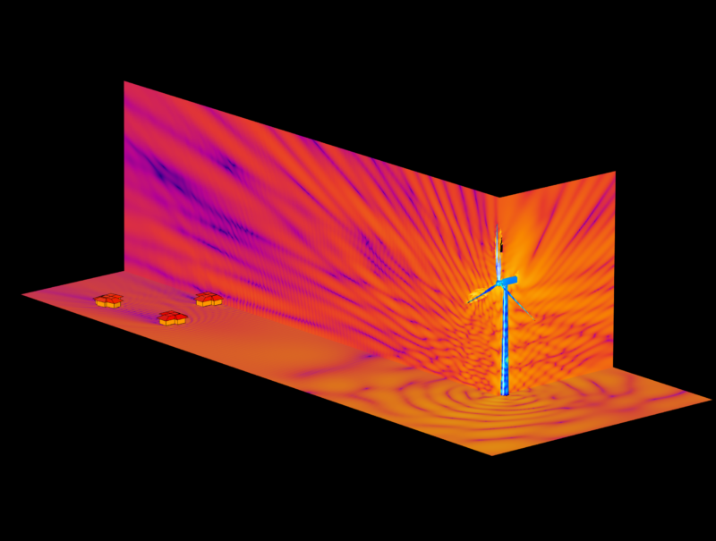
- The volumetric mesh naturally supports cross sections and full field contour plots
- It is straightforward to show sound pressure distribution around the turbine on arbitrary slices
With BEM:
- Results are defined on the boundaries
- To create similar contour plots, you must define grids of receiver points and compute sound level at each, adding post processing time
For many projects, that trade off is worth making because BEM delivers results quickly at the frequencies of interest. The important point is to plan from the start how results will be used in planning submissions, design reviews and communication with non specialist stakeholders.
Beyond FEA and BEM: very high frequencies
At very high frequencies, even BEM starts to struggle. Models become too large and solution times lengthen again.
In those regions, techniques such as:
- Statistical Energy Analysis (SEA)
- Ray tracing and other high frequency asymptotic methods
may be more appropriate. These approaches treat sound more like rays or energy flows than waves, which is a good approximation when wavelengths are very small compared with geometry.
The practical takeaway is that no single method is best everywhere. A robust acoustic strategy often combines multiple techniques across different frequency bands.
How Xi uses measurement and modelling together
For all our wind turbine acoustics work, simulation is only half the story.
Xi’s standard approach includes:
- Field measurements of vibration and far field sound from operating turbines, carried out by engineers trained to work at height on real machines
- Measurements that conform to IEC 61400 11 for both broadband and tonal noise, so that results integrate with established industry practice
- Model calibration and validation against those measurements, rather than relying solely on theoretical inputs
This gives developers, owners and OEMs confidence that the simulated behaviour is anchored in reality, and that predicted changes will translate into real world improvements.
How Xi supports wind turbine manufacturers and developers
Xi Engineering Consultants works across the wind sector, from single turbine troubleshooting to large onshore and offshore wind farms.
On wind turbine acoustics and noise modelling, we can help you to:
- Understand and reduce tonal noise risk
Identify sources of tonal components, explore design changes and quantify their likely impact at receptors. - Select the right modelling strategy
Choose between FEA, BEM and higher frequency methods, and design models that are efficient, robust and fit for purpose. - Integrate acoustics into turbine and wind farm design
Feed acoustic constraints into structural, control and layout decisions, rather than treating noise as an afterthought. - Support planning and stakeholder engagement
Present complex acoustic predictions in clear, visual formats that planners, communities and regulators can understand. - Extend methods to other large scale acoustic problems
Apply the same techniques to automotive cabins, large industrial structures or high end audio systems where physical size and frequency range create similar challenges.
You can bring us in for a focused tonal noise investigation, a model build for a new platform, or as a long term partner across multiple projects.