Despite the significant benefits of using mathematical models to help reduce the time and costs in the manufacturing process of liquid crystal displays (LCDs), there remains significant challenges in the modelling of such materials. One such challenges from a modelling perspective is that they are governed by many different aspects of physics, including electrostatics, optics, fluid dynamics, non-linear elasticity, ionic effects, flexoelectricity, acoustics, thermodynamics, and so on. Such a highly coupled non-linear physics system means that to try and solve as complete a mathematical model of liquid crystals as possible renders traditional pencil and paper methods ineffective and paves the way for powerful numerical software packages to try and undertake such complicated mathematical modelling. One of Xi Engineering Consultants specialities is using numerical simulations, in particular COMSOL Multiphysics, to advise clients in helping them in the development of their products and understanding behind the physics of their engineering system. It is our experience and background in working over a wide range of disciplines in physics and in using simulation software packages with in-built physics modules which makes us a suitable partner to help advise those working in the field of LCDs.
This blogpost will consider relatively simple mathematical models of LCDs, with only effects due to elasticity, electrostatics, and fluid flow considered. For each of these areas, a connection will be drawn as how to incorporate these effects into a COMSOL model. The results presented here will consider the advantages/disadvantages of 1D and 2D modelling to achieve optimal switching in displays.
Basic Operation of a Liquid Crystal Display
A typical LCD consists of the following components:
- Two substrates at the top and bottom of the device, which are usually made of glass or plastic.
- Electrodes which are deposited onto the surface of the substrate
- A layer of liquid crystal in the middle of the two electrodes
- Polarising filters which allow for the entrance and exiting of light

Figure 1 – Schematic figure of the operation of a simple liquid crystal display when an electric field is switched off (A) and then switched on (B) (Figures adopted from https://physicsopenlab.org/2020/03/30/liquid-crystals-and-electro-optic-modulation/).
The reason why liquid crystals are used for display technology purposes is firstly because of their ability to switch between different optical states when an electric field is applied. Secondly, they are an example of an anisotropic material (i.e., physical properties such as viscosity, elastic coefficients, dielectric permittivity, etc.) are directionally dependent.
AN LCD projects an image from a source of light which moves through a polarizer and lower substrate, into the liquid crystal layer. The polarizer restricts the amount of light which passes through to a single plane, leading to plane polarised light. The liquid crystal molecules are aligned along the surface of the substrates through physical rubbing, where rubbing in different directions can lead to different orientations in the liquid crystal cell. A sufficiently high voltage is applied to a liquid crystal sample to change the orientation of the molecules and allow for light to reach the upper substrate. A colour filter is included before a second polarizer filter to create the colours and images seen on an LCD. These images consist of an array of pixels, where each of the individual pixels can be switched on or off very rapidly to create a moving colour picture.
Fundamentals Behind Dynamic Theories of Liquid Crystals
The continuum dynamic theory of liquid crystals is underpinned by a quantity which governs the average preferred direction of liquid crystal molecules, known as the director, n. This quantity is a unit vector (i.e., n .n = 1) and is non-polar (i.e., there is no physical distinction between n and – n). The following subsections discuss elastic, electrostatic, and fluid flow effects in liquid crystals, and how they are integrated into a continuum theory to describe liquid crystal hydrodynamics. In this blogpost, the Ericksen-Leslie continuum theory are coupled with Maxwell’s equations to investigate the hydrodynamics in a standard nematic cell.
Elastic Distortion
One of the characteristic features of a nematic liquid crystal is the ability to maintain permanently an internal elasticity due to persistent elastic distortions of the director structure. The associated energy density in its simplest form is known as the Frank-Oseen energy density and is given by

where each of the different possible distortions in the liquid crystal director are pre-multiplied by an associated elastic coefficient K. Each of these constants are of order 1pN – 10 pN.
Electrostatics
When a voltage is applied across a sample of liquid crystal, the electric field E will tend to distort the distribution of charges within a group of liquid crystal molecules, creating a dipole moment known as a polarisation. How easily the charges can be redistributed parallel and perpendicular to the director, relative to the permittivity of free space ε0 = 8.85 pF/m is governed by the dielectric anisotropy coefficient Δε. The electric energy density associated with an applied electric field is

where a positive/negative value of Δε means the director prefers to align parallel/perpendicular to the electric field. In this report, Δε is set as positive.
Viscous Dissipation
In an incompressible isotropic fluid, the dynamics for the fluid velocity and pressure are governed by the Navier-Stokes equations. In a nematic liquid crystal, the viscous stress tensor for an isotropic liquid is extended to include contributions due to director orientation which couple to the fluid velocity. The resultant viscous stress tensor is skew-symmetric and can be written in terms of the viscous dissipation function

Each of the coefficients γ and η are nematic viscosities, with η3 representing the viscosity coefficient used in the Navier-Stokes equations for an isotropic liquid.
Ericksen-Leslie Equations
Since the 1930s, there have been numerous theories of liquid crystals, each of which have their own complexities. The first accepted dynamic theory of liquid crystals, namely the Ericksen-Leslie theory, was first developed by Jerry Ericksen in 1961 and completed by Frank Leslie in 1968 (see Figure 3) and is still adopted by mathematicians, engineers, chemists and experimentalists in current research.

Figure 2 – Pioneers of the Ericksen-Leslie dynamic theory of liquid crystals. Frank Leslie (left) and Jerald Ericksen (right). (Figure adopted from R.J. Atkin and T.J. Sluckin, Biographical Memoirs of Fellows of the Royal Society, pp 315 – 333, 2003).
The Ericksen-Leslie theory for an incompressible (i.e., constant fluid density) nematic liquid crystal in the isothermal case consists of the conservation laws from continuum mechanics of mass, angular momentum, and linear momentum, with equations to solve for the director orientation, fluid velocity, and pressure. Each of these conservation laws for a nematic are provided below, along with the corresponding COMSOL Modules used.
- Conservation of mass – use the Laminar Flow COMSOL Module

- Conservation of angular momentum – use the General PDE COMSOL Module

- Conservation of linear momentum – use the Laminar Flow COMSOL Module

Maxwell’s Equations
To model effects due to an electric field in nematics, the Ericksen-Leslie equations are coupled to Maxwell’s equations. In the absence of any free charges, which is a common modelling assumption to adopt, the equations for the electric field are

The Electrostatics COMSOL Module is used to model the electric field effects in the device, as well as in any PI layers and substrates included in the model.
COMSOL 2D Modelling Results
Numerical solutions of the Ericksen-Leslie equations for the director orientation, fluid velocity, and pressure, and Maxwell’s equations for the electric field for a 2D model of a nematic liquid crystal sandwiched between two substrates with a time-dependent voltage signal (see Animation 1) applied to the upper electrode are shown in Animation 2 – Animation 5. The chosen voltage signal on the upper electrode takes the form of a ramp function which increases towards its maximum switch-on value and is then gradually reduced to the switch-off situation. The lower electrode has zero voltage across it. It is a common modelling assumption that a constant voltage is used to reduce the complexity of the model. Using a time-dependent signal is representative of what experimentalists would use to switch on their displays, and can take different forms (i.e., ramp functions, square waves, etc.). For each of the unknown variables, standard boundary conditions are adopted (i.e., weak surface anchoring of the director orientation with anti-parallel rubbing along the substrates, no-slip and no penetration conditions for the velocity, and a period condition of zero pressure difference for the pressure).
The switching in the nematic occurs since a sufficiently high voltage is applied. The critical voltage at which the switching occurs has been predicted analytically and is referred to as the Freedericksz transition, which depends on the nematic material parameters via

At this critical voltage, the undistorted structure (i.e., constant director orientation across the channel) becomes unstable, and the distorted state, which minimises the free energy, becomes the stable configuration. As the voltage continues to increase beyond the Freedericksz transition, the director responds by aligning closer to the direction of the electric field for positive Δε such that in most of the channel, the director orientation in the bulk of the channel increases towards θ = π/2, constrained at the boundaries due to surface anchoring. Once the liquid crystal reaches its switch-on equilibrium configuration, the voltage on the electrode is switched off.

Animation 1 – Time dependent voltage signal applied to the upper electrode of the liquid crystal device.

Animation 2 – Evolution of the director angle across the liquid crystal layer as the voltage signal in Animation 1 is applied to the upper electrode.
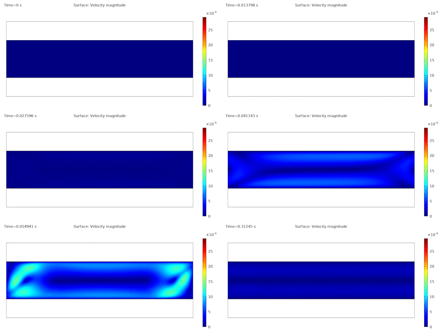
Animation 3 – Evolution of the fluid velocity magnitude across the liquid crystal layer as the voltage signal in Animation 1 is applied to the upper electrode.
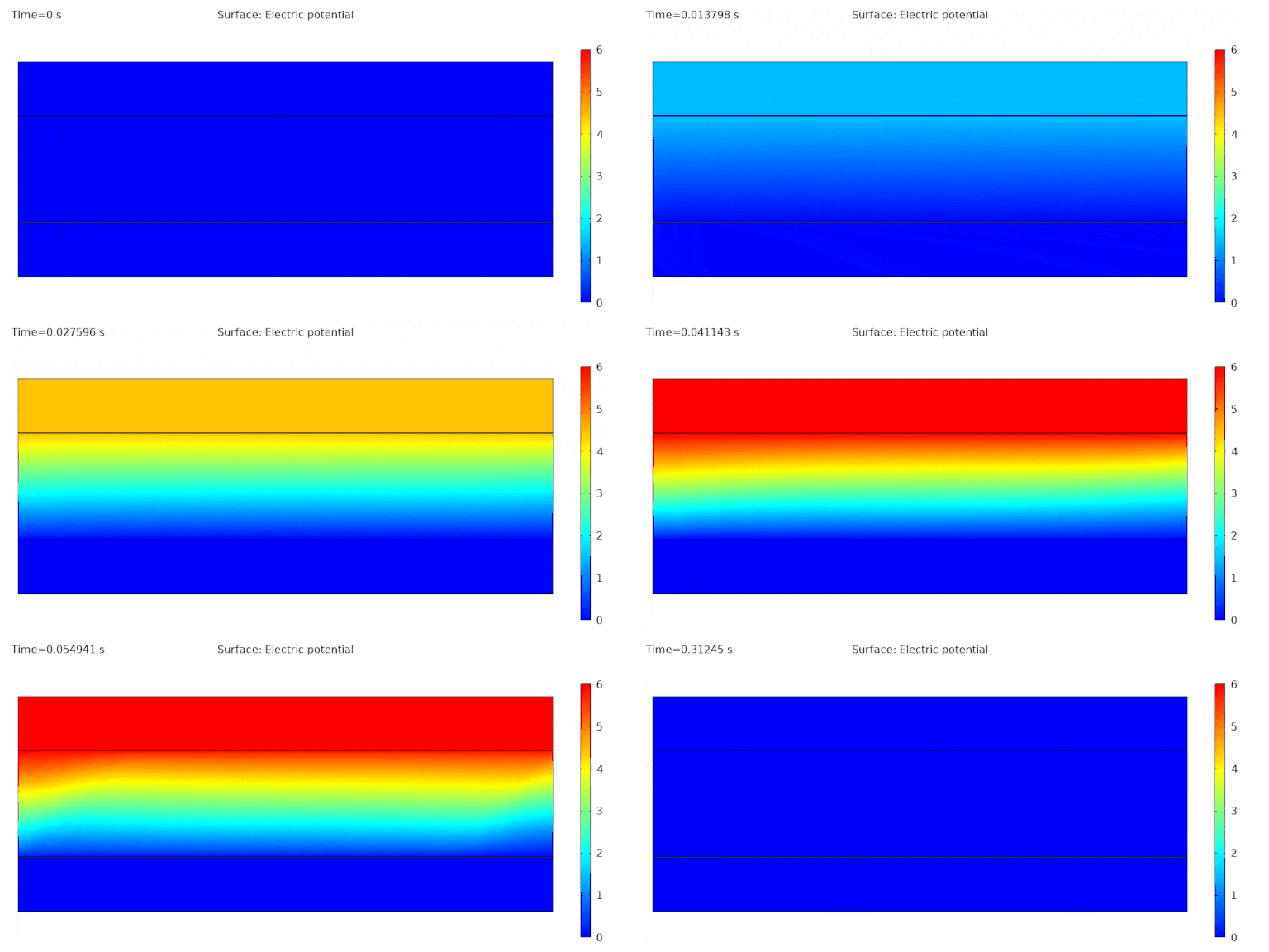
Animation 4 – Evolution of the electric potential across the liquid crystal and PI layers as the voltage signal in Animation 1 is applied to the upper electrode.
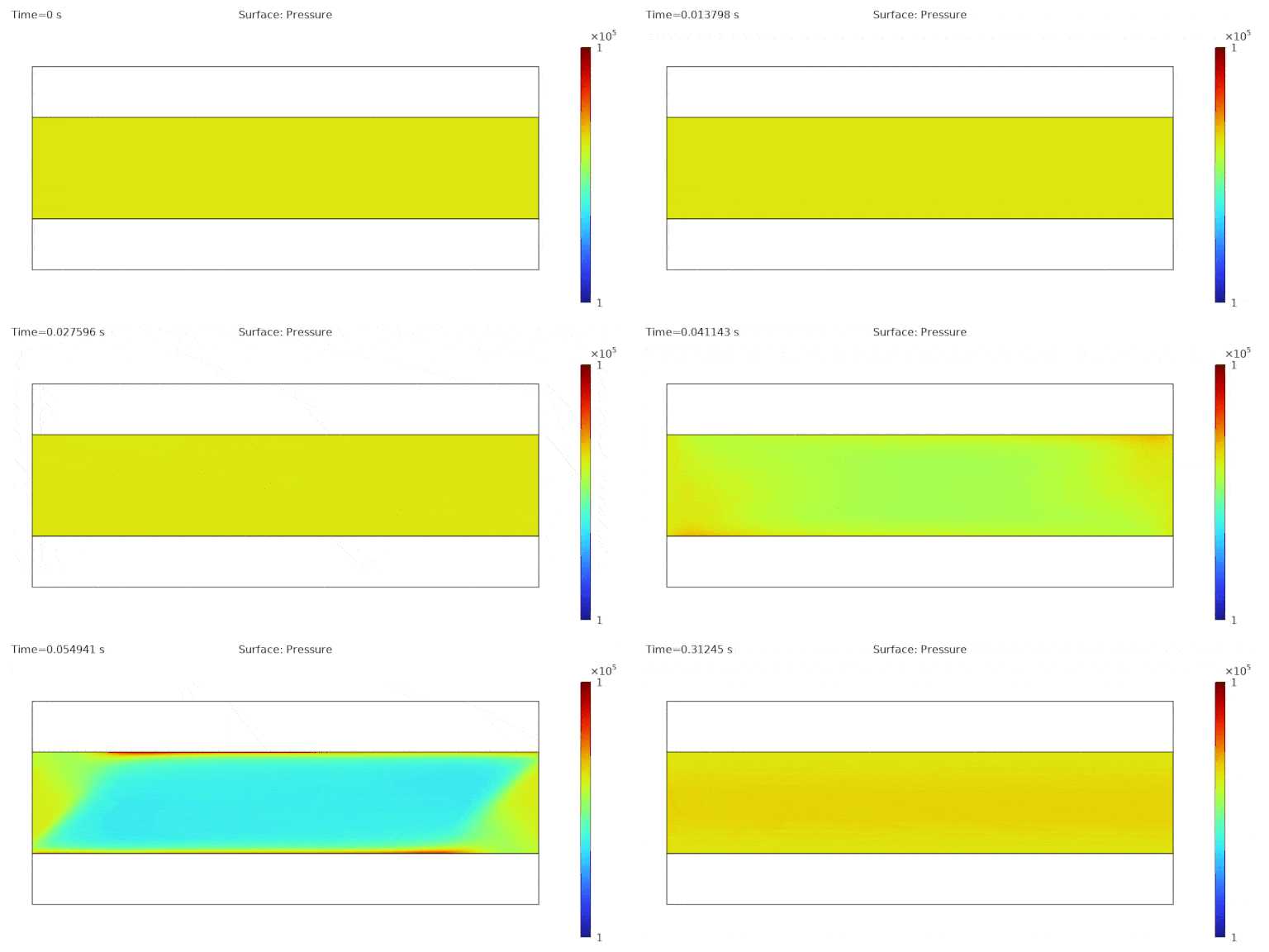
Animation 5 – Evolution of the pressure across the liquid crystal layer as the voltage signal in Animation 1 is applied to the upper electrode.
Benefits of Reverting to a 1D Model
One of the features that we find from this model is that as the voltage signal amplitude begins to reduce from its peak, instead of the configuration for the director orientation and flow reverting to what they were before the field was switched-on, there is an increase in the director orientation at the channel centre, which leads to the generation of flow (i.e., backflow). This is more clearly seen from Animation 6, which show both the director angle and its time derivative as a function of time. This initial increase is referred to as kickback and causes a slowing down in the switching of the display, which is unwanted for optimal device performance.
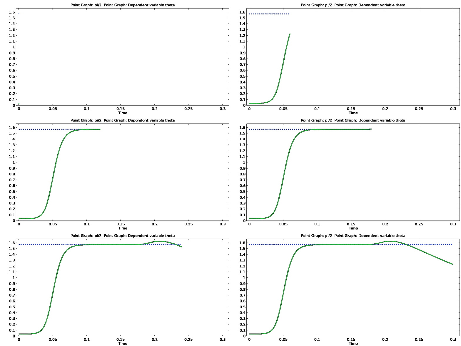
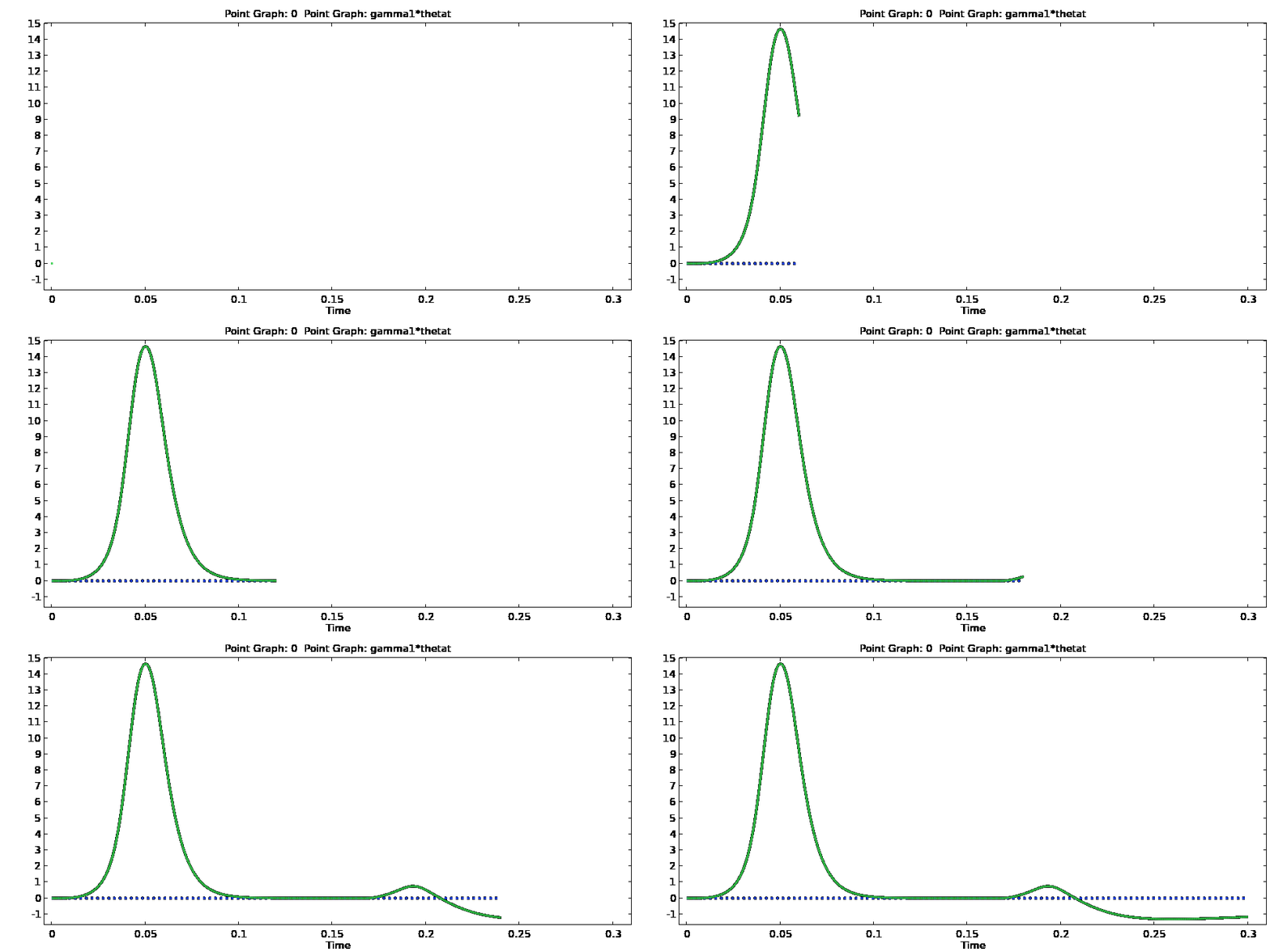
Animation 6 – Evolution of the director angle (top) and its time derivative (bottom) at the channel centre when the voltage signal in Animation 1 is applied to the device. Once the signal is switched off, there is an initial increase in both before the liquid crystal begins to revert back to its pre-switched configuration.
The difficulty in trying to work out which parameter combination will help give the optimal switching using a 2D model is the computational cost. It is therefore beneficial to revert to a 1D model where computational costs are significantly less and allow more extensive parameter testing (i.e., material properties, cell dimensions, surface energies, applied voltages, etc.) to achieve the best switching. To illustrate this, Figure 4 shows the time derivative of the director angle in the channel centre over a range of switch-on voltages using a 1D model with different surface energies along the liquid crystal layer boundaries. What these results highlight is what range of voltages you would want to consider to achieve the fastest switching (areas marked red), whilst those marked green indicate where the switching would be slowed down due to kickback. This takes significantly less time using a 1D model compared to when the same material properties are considered in the 2D model which is advantageous. The advantage of using a 2D model is that it will generate a more accurate representation across the display. There is very good agreement between the 1D and 2D models, both of which show that when a switch-on voltage of 6 Volts is used, the switching will take longer compared to using a smaller voltage. The 1D model suggests that a switch-on voltage of approximately 1.25 Volts will give the optimal switching at the chosen nematic and geometric parameters which can then be tested using a 2D model.
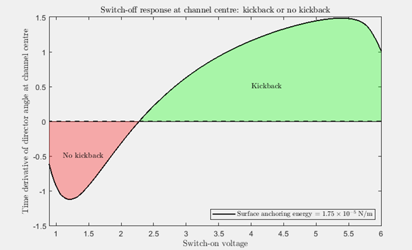
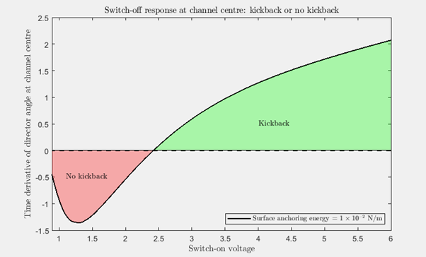
Figure 4 – Variation of the time derivative of the director angle at the channel centre as a function of maximum switch-on voltage once the electric field is turned off using weaker surface anchoring (top) and stronger surface anchoring (bottom).
Xi Engineering’s Expertise and Capabilities
One of Xi Engineering Consultants areas of expertise is undertaking numerical simulations of complicated engineering systems. Our team has experience in using COMSOL Multiphysics across a range of engineering disciplines including acoustics, solid mechanics, electrostatics, fluid mechanics, batteries, superconductors, semiconductors, and so on. If you have a project involving liquid crystals, or indeed any other form of anisotropic fluid, in which a mathematical model would be either essential or beneficial in anyway, then get in touch.


