
Motorcycle drive cycle measurement to validate simulation models
To validate its motorcycle power and torque model, Xi Engineering Consultants instrumented a real bike on urban and extra urban routes, measuring motion, loads and wind conditions to tune the software against real world behaviour.
The Challenge
The analytical tool developed for Edge Mobility relied on physics based calculations of forces along a drive cycle. To be truly useful in design, it needed to match reality, not just theory. That required detailed measurement of how a real motorcycle behaved over representative routes, including aspects such as wind, gradient, suspension movement and tyre behaviour that are difficult to infer from standards alone. Xi needed a measurement strategy that could capture all relevant parameters synchronously at sufficient resolution while the bike followed pre defined drive cycles, and a way to feed that data back into the model for validation and refinement.
Our Approach
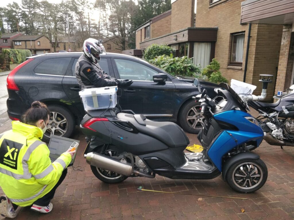
To validate the motorcycle model, Xi designed a measurement campaign that captured how a real bike behaved on representative urban and extra urban routes. An AIM EVO 5 data logger was mounted on the motorcycle as a central hub, linked to GPS, gyroscopes, wheel speed sensors, suspension potentiometers, tyre pressure sensors and an anemometer. Together these instruments recorded position, speed, acceleration, attitude, wheel motion, tyre pressure and wind conditions at 10 Hz while the rider followed pre defined drive cycles. After each run, data was transferred wirelessly to a laptop, where it was processed and fed back into the simulation, allowing the model to be tuned until it reflected real world behaviour.
The Results
Why it matters
Models are only as good as their validation. For new electric vehicle concepts, capturing representative drive data and closing the loop between measurement and simulation is essential if tools are to guide real design choices. This case shows how Xi combines instrumentation, data logging and analysis to ground its Multiphysics models in reality, reducing the risk that low carbon vehicles disappoint once they leave the lab.